

















Whether you're salvaging a screen from old equipment or verifying a replacement before installation, knowing how to test a 31-pin RGB/TTL LCD panel without a motherboard is an essential skill for technicians and DIY enthusiasts. Here's a practical, step-by-step guide
 .
.
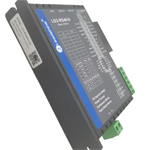
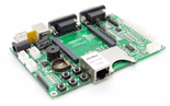
Universal LCD signal generator / multi-interface driver board (supports RGB/TTL 31-pin)
Adjustable DC power supply (typically 3.3V or 5V — check your panel's datasheet)
31-pin flat ribbon cable
Backlight inverter or LED driver (if backlight is separate)
Multimeter for voltage verification
Power: VCC (3.3V/5V), GND
Data: R0–R5, G0–G5, B0–B5 (18-bit color)
Control signals: HSYNC, VSYNC, DE (Data Enable), PCLK (Pixel Clock)
Backlight: VLED+/VLED− (on some variants)
⚠️ Always confirm pinout against your specific panel's datasheet before powering on.
Identify the pinout. Download the datasheet for your panel. For example, the popular Samsung LTM150X2-04 uses a 31-pin RGB/TTL interface with a well-documented pin configuration.
Connect the driver board. Align the 31-pin ribbon cable to the universal driver board's TTL output header. Ensure pin 1 orientation matches.
Set the correct voltage. Use your multimeter to verify the power supply matches the panel's rated VCC (the LTM150X2-04 operates at 3.3V logic / 5V backlight).
Power the backlight separately. Connect the inverter or LED driver to the backlight pins. You should see an even glow before any image appears.
Input a test signal. Select the correct resolution on your signal generator (e.g., 1024×768 XGA for the LTM150X2-04). A test pattern or color bars should display.
Inspect for defects. Check for dead pixels, vertical/horizontal lines, uneven brightness, or color banding.





