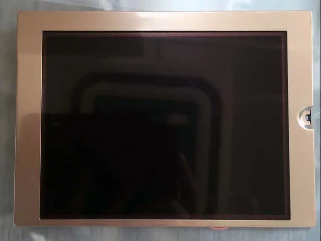
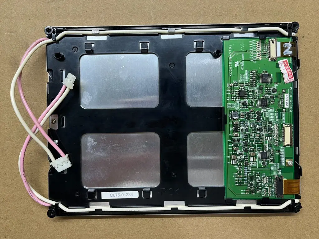
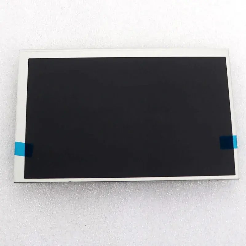
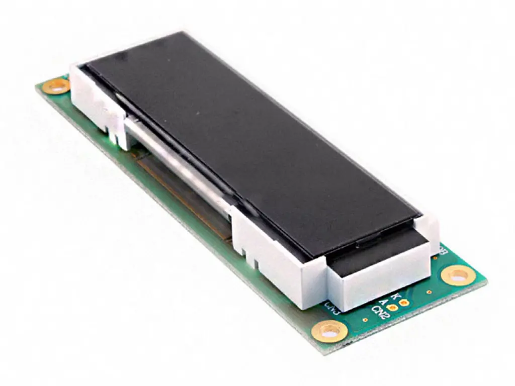
Kyocera KG057QVLCD-G310 5.7" Industrial LCD Display Panel 320×240 Color
The KG057QVLCD-G310 is a 5.7" industrial LCD display panel manufactured by Kyocera, featuring QVGA resolution (320x240) with Monochrome display and WLED backlight. With 230 cd/m² brightness and 4:1 contrast ratio, viewing angle 45/45/20/40, Parallel Data interface, designed for industrial instrumentation, embedded systems, and reliable display applications.
| Brand | Kyocera |
| Model | KG057QVLCD-G310 |
| Size | 5.7" |
| Resolution | 320×240 |
| Brightness | 230 cd/m² |
| Contrast Ratio | 4:1 |
| Viewing Angle | 45/45/20/40 |
| Display Type | Monochrome |
| Backlight | WLED |
| Interface | Parallel Data |
Industrial instrumentation and gauges
Embedded systems displays
Metering equipment
Point-of-sale terminals
Security alarm panels
Small appliance displays
FAQ:
Q1: What is the key difference between the KG057QVLCD-G310 and the older G060 model?
A1: The most significant difference is the backlight. The “-G310” suffix indicates that this model utilizes a modern LED backlight, whereas the older “-G060” used a CCFL (Cold Cathode Fluorescent Lamp) backlight. This means the G310 does not require a high-voltage inverter, consumes significantly less power, generates less heat, and has a much longer operational lifespan.
Q2: What type of interface does this display panel use?
A2: The KG057QVLCD series typically uses a Digital TTL/CMOS RGB interface. It receives parallel digital data (usually 6-bit or 8-bit per color channel) along with standard synchronization and clock signals (HSYNC, VSYNC, DOTCLK, and Data Enable). It is designed to be driven directly by an industrial SoC or microcontroller with a built-in LCD controller, rather than an analog VGA output.
Q3: Can I use the G310 to replace a damaged G060 in my machine?
A3: Not directly. While the front viewing area and mounting holes may be identical, the electronics are different. Your existing G060 setup includes a high-voltage CCFL inverter that the G310 does not need. You would need to bypass the inverter and supply the correct low-voltage DC power to the G310’s LED driver circuit. Furthermore, you must verify the connector pinouts and signal timings in the datasheets, as the two revisions often use different FPC/FFC cable layouts.