


- Industrie-LCD-Display
-
Industrial Products
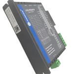
- DC Servo Drive
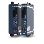
- AC Servo Drive
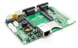
- PCB
- Siemens
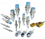
- Switch Sensor
- Näherungsschalter
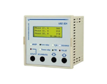
- Temperaturregler
- Schutzrelais
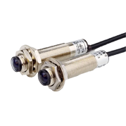
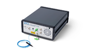
- Fiber Optic Sensor
- Encoder
- Fan
- other
- Heidelberg
- MITSUBISHI
- FANUC
- Siemens adapter
- Fujitsu connector
- Der Aufsichtsrat
- Board
- Contactor
- Circuit
- Omron
- Relais.
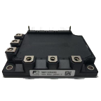
- Motortreiber
- power supply
- Cable
- Transformator
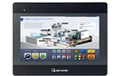
- HMI Touch-Glas
-
HMI-Vollautomat Ganze Einheit
- OMRON HMI Touch Panel
- Siemens HMI Touch Panel
- Mitsubishi HMI Touch Panel
- Allen-Bradley Automatisierung HMI Touch
- DELTA HMI Touch Panel
- EVIEW DELTA HMI Touch Panel
- KINCO DELTA HMI Touch Panel
- HITECH HMI Touch Panel
- WEINTECK HMI Touch Panel
- TECVIEW HMI Touch Panel
- WEINVIEW HMI Touch Panel
- PANASONIC HMI Touch Panel
- KYOCERA HMI Touch Panel
- SCHNEIDER HMI Touch Panel
- Module
- LCD Wechselrichter
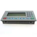
- Membran Tastenfeld Schalter
- Winni Touch Screens
- Frequenzumrichter
- Servo Motor
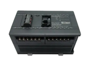
- PLC
In the intricate world of embedded systems and custom display solutions, the selection of a display module is a critical decision that balances technical specifications, integration complexity, and cost. The AT070TN83, a 7.0-inch TTL LCD panel from Innolux, paired with a compatible driver board, represents a cornerstone component for engineers, hobbyists, and product developers. This combination offers a direct path to implementing a vibrant visual interface in a compact form factor.
This article delves deep into the AT070TN83 ecosystem, moving beyond basic datasheet parameters. We will explore its core technology, the indispensable role of the driver board, and the key considerations for successful integration. From interface protocols to power management and practical application niches, this guide aims to provide a comprehensive resource for anyone looking to harness the potential of this specific display solution, ensuring an informed and successful implementation in your next project.
Understanding the AT070TN83 LCD Panel Core
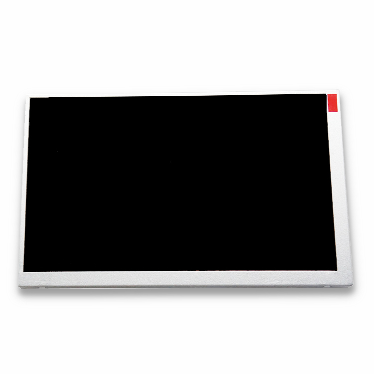
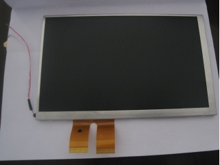
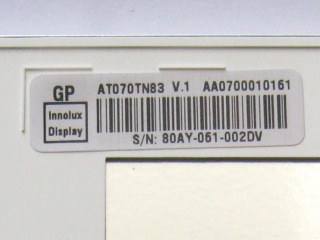
The Innolux AT070TN83 is a 7.0-inch diagonal liquid crystal display panel with a native resolution of 800 x RGB x 480 (WVGA). Its "TTL" designation is the first crucial detail: it signifies a Transistor-Transistor Logic interface. Unlike modern LVDS or eDP panels that serialize data for noise reduction, a TTL interface transmits parallel RGB data signals. This means it requires a significant number of pins (often 40 or more) to carry the color information for each pixel clock cycle.
The panel itself is a passive component, containing the color filters, liquid crystal matrix, and backlight unit. It features a typical brightness of 300 nits, a contrast ratio of 500:1, and a wide viewing angle. Understanding that the raw panel only accepts specific TTL voltage-level signals is key; it cannot connect directly to standard video outputs from boards like the Raspberry Pi or FPGA dev kits without translation. This inherent characteristic directly necessitates the next core component: the driver board.
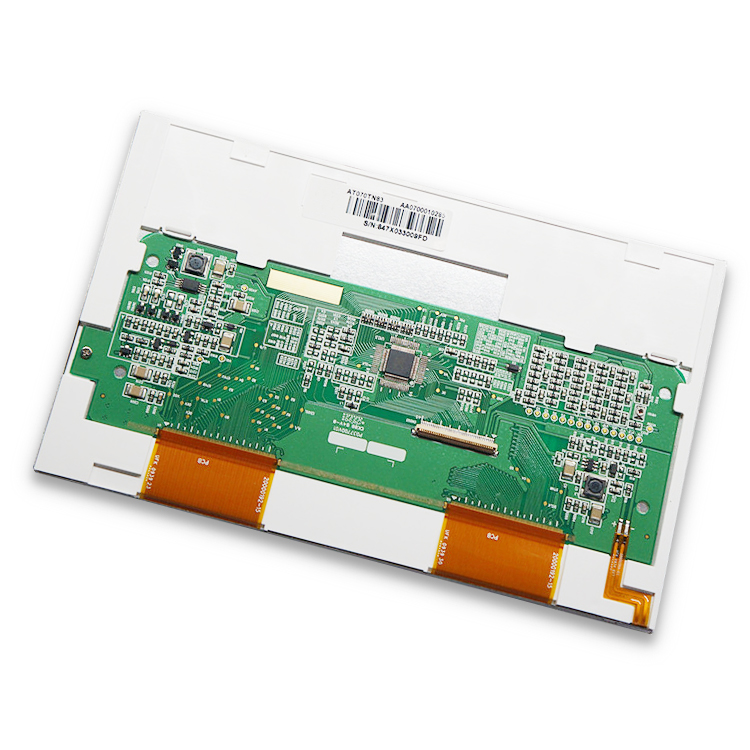
The Critical Role of the Driver Board
The driver board, often called a controller board or LCD interface board, is the active brain that makes the AT070TN83 panel functional. Its primary mission is to bridge the gap between a host device's video output and the panel's strict TTL input requirements. Most driver boards designed for this panel accept more common video input signals, such as HDMI, VGA, or LVDS, and convert them into the precise parallel TTL timing and voltage levels the AT070TN83 understands.
These boards are not simple pass-through adapters. They contain a dedicated timing controller (TCON), power regulation circuits, and often a microcontroller for managing settings like brightness and contrast via on-screen displays (OSD). Selecting the correct driver board is as important as selecting the panel itself. It must match the panel's resolution, interface type (40-pin TTL), and backlight voltage requirements. A mismatch can lead to no display, incorrect colors, or permanent damage.
Interface Protocols and System Integration
Integrating the AT070TN83 with a driver board into a larger system requires careful planning around the interface protocol. While the panel side is fixed as TTL, the input side of the driver board offers flexibility. For modern single-board computers (SBCs) like the Raspberry Pi, an HDMI-input driver board is the most straightforward choice, providing a plug-and-play experience. For legacy industrial systems, a VGA input might be necessary.
For deeply embedded applications where size and power are constrained, some driver boards offer LVDS input, which can be generated by certain microprocessors or FPGAs, creating a more robust and lower-noise link between the main processor and the driver board than long TTL cables would allow. The integration extends to physical mounting, ensuring the board's form factor fits the enclosure, and managing the cabling for power, video input, and potential touch screen overlays to avoid electromagnetic interference.
Power Requirements and Signal Integrity
Reliable operation of the AT070TN83 and its driver board hinges on stable power and clean signals. The system typically requires two main voltage rails: a low-voltage logic supply (e.g., 3.3V or 5V) for the driver board's ICs and a higher voltage (often 12V or directly from a backlight driver) for the LCD's backlight LEDs. Using a power supply with adequate current headroom and low ripple is crucial to prevent display flicker or noise.
Signal integrity is paramount, especially on the TTL connection between the driver board and the panel. This wide, parallel bus is susceptible to crosstalk and electromagnetic interference (EMI). It is essential to use the manufacturer-recommended shielded flex cable or ribbon cable, keep the cable length as short as possible, and avoid routing it near noise sources like switching power supplies or motors. Proper grounding of both the driver board and the host system is a non-negotiable step for a stable image.
Application Scenarios and Practical Use Cases
The AT070TN83 with a driver board finds its niche in applications where its specific combination of size, resolution, and interface is optimal. It is a popular choice for retrofitting older industrial equipment that originally used CRT monitors, as a VGA-input driver board provides a direct drop-in LCD upgrade. In the maker and hobbyist community, it enables custom portable consoles, home automation control panels, and embedded project dashboards.
Furthermore, it serves in prototyping and low-to-medium volume production of human-machine interfaces (HMIs) for medical devices, test instruments, and point-of-sale systems. Its 7-inch size is large enough for clear interaction yet small enough for portable or space-constrained devices. The availability of driver boards with resistive or capacitive touchscreen interfaces expands its utility to interactive kiosks and handheld terminals.
Selection Criteria and Sourcing Considerations
When procuring an AT070TN83 solution, several factors must guide your decision. First, verify the exact panel model and revision, as pinouts can change. Second, choose a driver board based on your host's video output (HDMI, VGA, etc.), required additional features (touch controller, audio, OSD buttons), and physical dimensions. Third, assess the quality of support, including availability of datasheets, firmware updates, and technical documentation from the driver board vendor.
Sourcing can be done through major electronics distributors or specialized display module suppliers. Be wary of "compatible" boards that may use lower-quality components or have poor firmware. Requesting a sample for testing in your actual application environment is highly recommended to validate compatibility, image quality, and thermal performance before committing to volume purchases.
Frequently Asked Questions (FAQs)
Q1: Can I connect the AT070TN83 directly to a Raspberry Pi?A: No. The Raspberry Pi's video output (HDMI or DSI) is not compatible with the panel's TTL interface. You must use a compatible driver board that accepts HDMI input.
Q2: What does "TTL" mean in this context?A: It refers to the parallel digital video interface standard (Transistor-Transistor Logic) the native panel uses, requiring many data lines.
Q3: Is a driver board always necessary?A: Yes, for almost all applications. The driver board converts standard video signals to the specific TTL timing the panel requires.
Q4: What are common input options for the driver board?A: Most boards offer HDMI, VGA, or LVDS inputs. Choose based on your source device's output.
Q5: Does this setup support touch functionality?A: The panel itself does not, but many driver boards are available as kits that include a separate touch overlay (resistive or capacitive) and its controller.
Q6: What is the typical power consumption?A: It varies but expect roughly 3-5W for the panel and backlight, plus the driver board's own consumption. Always check your specific board's specifications.
Q7: Can I adjust the brightness?A: Yes, brightness is usually controlled either through the driver board's OSD menu or via an external PWM (Pulse Width Modulation) signal pin on some boards.
Q8: Why is my display showing a blurry or double image?A: This is often a timing mismatch. Ensure the driver board is configured or designed explicitly for the AT070TN83's 800x480 resolution.
Q9: Are the driver boards plug-and-play?A: Physically, yes—they connect directly. However, you may need to configure your source device (like a PC) to output the correct native resolution for optimal clarity.
Q10: Where can I find the pinout diagram for the panel?A: The official Innolux datasheet for the AT070TN83 contains the precise pinout. It is essential for custom driver board design or troubleshooting.
Conclusion
The Innolux AT070TN83 7.0-inch TTL LCD panel, when coupled with a well-matched driver board, forms a versatile and reliable display subsystem for a wide array of applications. Its value lies not in being the newest technology, but in offering a proven, direct solution for bridging modern video sources to a compact, robust display. Success hinges on understanding the symbiotic relationship between the passive panel and the active driver board, paying meticulous attention to interface selection, power quality, and signal integrity during integration.
By carefully considering the technical requirements outlined—from protocol conversion to physical mounting—developers can effectively leverage this display combination to create polished and functional user interfaces. Whether for revitalizing legacy equipment or prototyping the next generation of embedded devices, the AT070TN83 ecosystem remains a relevant and powerful tool in the display integrator's toolkit.